Drawing Paths
The basic way is: select a path/relationship tool (1), move cursor to the start element (2), press and hold left mouse button and move to the end element (3). After releasing the button, the relationship between these elements will be created.
If you don't start (and/or end) the path directly over the element, but only near to it, the program will automatically recognize what you wanted to do and connect the correct elements:
You can also use drag&drop technique (as by shapes) – press and hold left mouse button over chosen relationship tool (1) and move the cursor to free space between two elements and then release the button (2).
If the relationship is not same on both ends or program is not sure which two elements you want to connect, New Relation dialog will show, where you can adjust the start (1) and end element (2) of relationship. The most probable option is predefined. If you want to change only the direction of relationship you can click on the double-arrow button (3). After clicking OK button, the relationship will be created.
The Smart key feature is available also for relationships. Press the key shortcut for the tool, you want to use, and the program offers you several (max. 10) possible relationships. Press the numeric key (0-9) to select the option you want.
If you want to draw a complex rectangular path, you can use the freehand drawing feature. Select the desired relationship tool in the toolbox (1). Move mouse cursor to the start element (2). Press and hold right mouse button, draw any custom path, which will end over the end element (3). Release the mouse button. The path will be automatically adjusted and the relationship between elements created.
The drawn rectangular path can be adjusted – you can move vertical lines to left or right (1), horizontal lines up or down (2) or you can adjust the position of breakpoints (3).
Line Styles
Paths can be routed in one of these five styles:
- Straight
- Oblique
- Curve
- Rectangular
- Round Rectangular

Straight
Straight style is a simple line without any breakpoints from one element to another.
Oblique
Oblique style allows to define custom path with unrestricted number of breakpoints.
Curve
Curve style allows to define custom path with unrestricted number of breakpoints. The path has smooth transitions around breakpoints.
Rectangular
Rectangular style restricts the path to horizontal and vertical lines.
Round Rectangular
Round rectangular style is similar as Rectangular, the only difference are the rounded corners.
Change Line Style
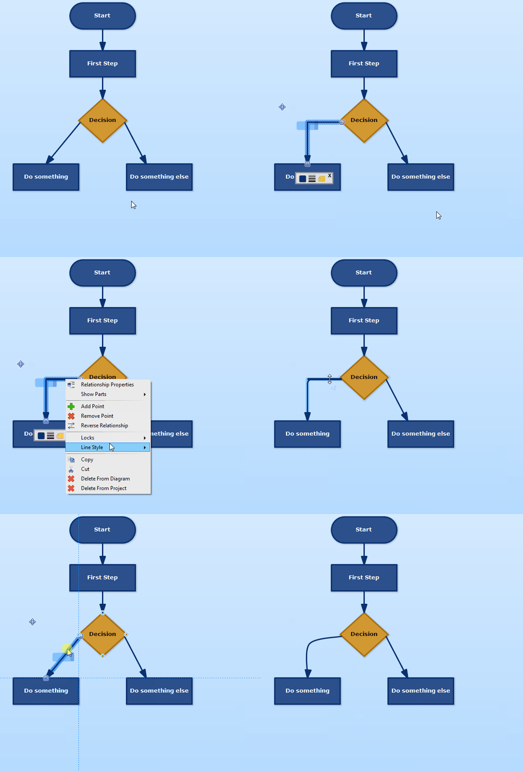
If you want to change the style of path, right click on line and in context menu, click on Line Style and choose one of items in submenu (Straight, Oblique, Rectangular, Rounded Rectangular, Curve).

Claudia 6 April 2016 9:15:59
Remove connecting lines of connection elements
Dusan Rodina - softwareideas.net 6 April 2016 21:48:08
RE: Remove connecting lines of connection elements
Claudia 11 April 2016 14:53:34
RE: RE: Remove connecting lines of connection elements