Drawing Diagrams - How to Draw Diagrams (Day 2)
Add New Empty Diagram
There are many ways how to add a new diagram. The easiest one is to click on the Plus button after the last tab or using the shortcut keys CTRL+D. The Diagram menu will show. It offers the diagram types organized in groups. You may scroll to the desired type of diagram and click on its item to add it to the project and start its editing. If you want to add a diagram like a pro, you may type its name and press enter. If you want to be even faster, type just its acronym (e.g. ad for Activity Diagram, cd for Class Diagram, uc for Use Case Diagram).
The new diagram will be added to the active project folder. By default, there is a folder called “Model1” in the project. You may add other folders and nest them to create hierarchies.
The diagram types you create most often are listed in a special group called Favorite. There are up to five different diagram types.
Creating Diagram Content
After adding a diagram to your project, there is a blank canvas before you. Now, it is up to you to fill it with content. You may add boxes, shapes and connect them with lines – relationships, connectors. This may be done in different ways – the one you would prefer will probably depend on your former experiences with other diagramming or drawing tools. But no worries – Software Ideas Modeler covers many popular techniques.
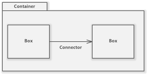
Basic Element Categories
- Box/Node
- Connector/Relationship - connects two nodes
- Container - may contain other nodes
How to Add Boxes to Diagram
Firstly, you should add some boxes (nodes, e.g. classes) to your diagram. You may do it in various ways:
- Drag & drop – to add a node element to a diagram, drag the desired element button from the toolbox and drop it over a free space in the diagram. During dragging you will see the bounds of the placing element. The element is centered relative to the mouse pointer.
- On a click – select an element tool in the toolbox and click on a free space in the active diagram. The element will be inserted on the clicked position (the top left corner of the placed element will be on the clicked position).
- Draw bounds – press the left mouse button over a start position, hold the mouse button and move the cursor to an end position. By the dragging, you specify the bounds of an inserted element.
- Using keys – there is a feature called Smart Keys. It allows you to add an element using the keyboard. Press the key displayed in the right of the tool button in the toolbox. The software will offer you possible positions in the diagram. Press the number of the chosen position – the element will be inserted.
How to Add Connectors to Diagram
If you have placed some boxes in a diagram, you may want to connect them using connectors or relationships that most diagram types offer. The relationship connecting two elements may be added in one of these ways:
- Connect two elements – select a connector tool in the toolbox and start dragging from an element to another one (or even the same one – to create self-relationship).
- Drag & drop – drag a connector tool button from the toolbox and drop it between two elements to connect them or over an element to add a self-relationship to it
- Connect two elements and specify path – if you drag using the right mouse button from an element to another element, they will be connected and the connector will have the rectangular path specified by the mouse cursor moving during dragging.
- Using keys – using the Smart Keys feature you may add a connector between two specified elements. If you press a key (shown on the right of a connector tool in the toolbox), possible connector positions will show in the diagram with associated numbers. If you press the number key the connector will be placed on the particular position.
Add Multiple Elements in a Row
Normally, after using a tool, the active tool is switched back to the Selection tool. However, sometimes you may want to use the same tool multiple times in a row – e.g. add four new classes. You do not need to click on the desired tool again and again. If you double-click or click twice on the tool button in the toolbox, the tool gets locked. You may use it until you choose another tool manually by clicking its button.
How to Add Connected Element to Another Element in Diagram
Software Ideas Modeler allows you to do common actions effectively. You do not need to add an element first and then its connector to another element. You may do it in one step. There are two options on how to do it, using:
- Context bar – is usually displayed below the selected element. It offers popular actions you may do with the element. It may contain buttons for adding connected elements (e.g. sub/superclass together with its generalization relationship).
- Right drag & drop – if you drag a diagram element using the right mouse button to a new position, the program allows you to create a new connected element on the place where you released the mouse button. The context menu will show from which you may select the type of connection you want to insert to the diagram.
Common Diagramming Tools
Except for the tools for each element supported by an active diagram, the toolbox also offers a group of common tools. Most of them do not create an element in the diagram, but they provide other useful actions.
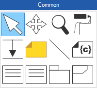
The toolbox offers these tools in the Common group:
- Selection – allows you to select an element or multiple elements.
- Pan – scrolls the view on the active diagram to any direction without bothering to accidentally move or change an element in the diagram
- Zoom – zooms to a specified area in the diagram. The area is specified by dragging as you would draw a box. If you click using the left mouse button, the diagram will be zoomed in, if you right-click, the diagram will be zoomed out.
- Freehand Path – redefines the path of an existing connector by drawing the path in the diagram.
- Move – moves parts of a diagram from a specified point to any direction (left/right/up/down) by the distance specified by dragging.
- Comment – adds a comment to the diagram
- Comment Connector – adds a comment connector to the diagram.
- Element Detail – adds an element that lists hidden attributes of the associated element.
- Diagram Description – adds a diagram description table to the diagram.
Specific Diagramming Tools
Each diagram type has its specific group of tools in the toolbox. It provides the tools for adding boxes/nodes and connectors/relationships of diagram-specific types.
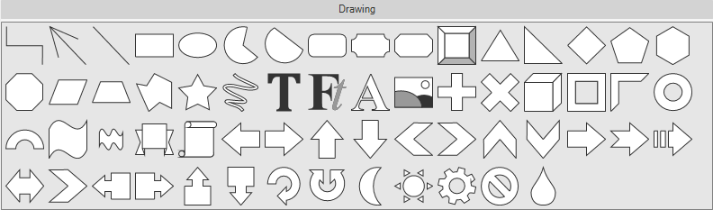
Shape Tools from Drawing Group
Software Ideas Modeler offers a rich group of shapes that may be added to any diagram. The shapes may be added to a diagram in the same way as other boxes/nodes and connectors do.
New Comment