UML Use Case Diagram Tutorial
What is a Use Case Diagram?
A use case diagram shows user interactions with a system. The diagram consists of block elements - actors (stickmen) and use cases (ellipses). Use cases are connected with actors using associations. A use case may include other partial use cases or extend other use cases. The diagram is utilized especially in the initial stages of software development.
Use Case Diagram in UML
A use case diagram is a behavior diagram. It is used for user requirement analysis. The functional user requirements are expressed through use cases. A use case diagram is a great tool for use case analysis.
Use Case Diagram Symbols
Software Ideas Modeler offers tools for following elements of a use case diagram:
- Actor
- Use Case
- Collaboration
- Association
- Include
- Extend
- Generalization
- Realization
- System Boundary
Actor
An actor represents a role in a system. It is not a specific user or person. It can be a human role, an external system, or an application.

Types of Actors
There are 2 main types of actors:
- Primary actors - start an interaction with the system. They work with core domain features.
- Secondary actors (or supporting actors) - the system start an interaction with them as a reaction to the actions of primary actors.
Categories of Actors
- Human users
- Software, services, systems
- Hardware
- Timer
Use Case
A use case represents the functionality of an analyzed system, it captures a requirement. It defines the interaction between a role (actor) and a system. It specifies actions which lead to achieving a goal.
Definition of Use Case
A use case has these parameters:
- Name
- ID
- Brief description
- Primary Actor
- Scope - it can be: organization black box, organization white box, system black box, system white box or component
- Level - it can be: very high summary, summary, user goal, subfunction or too low
- Precondition
- Postconditions
- Minimal guarantees
- Success guarantees
- Triggers
- Frequency of use
- Priority
- State - it can be draft, review, final or canceled
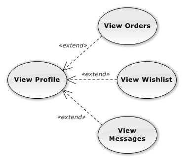
Extend
An extending use case extends the behavior of an extended use case. The extended use cases are dependent on the extending use case. An extended connector allows you to define an extension point, which refers to the step in the flow where the use case is extended.
The arrow of this relationship points from an extending use case to an extended use case.
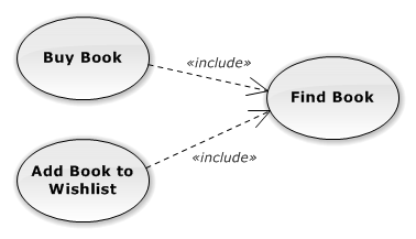
Include
An including use case is dependent on an included use case. The included use case is a mandatory part of the including use case.
The arrow of this relationship points from an including use case to an included use case.
System Boundary
A system boundary is a rectangular area which helps you to divide use cases into visual groups.
How to Draw a Use Case Diagram?
You can create a new use case diagram in multiple ways:
- Click on a Plus button in the tab switch bar, navigate to UML group and click on the UML Use Case Diagram item
- Press CTRL+SHIFT+D, choose Use Case Diagram from the UML group, enter the name, and click on the OK button.
- Switch to Project tab in the ribbon and click on the Use Case Diagram item in the Content gallery.
- Open Project sidebar, right-click on a project (or a folder) node, and in the Add Diagram submenu, choose UML Use Case Diagram.
How to Draw Use Case Diagram Elements?
How to Draw an Actor?
- Click on the Actor button in the Use Case Diagram group in the toolbox.
- Specify the bounds of the new actor by dragging on the diagram canvas.
- If you want to add an actor with the default size, just click on a diagram canvas and the actor will be inserted to the specified position.
- If you want to insert multiple actors in a row, double click (or click twice) on the Actor button in the toolbox and draw as many actors as you want in the diagram editor.
How to Draw a Use Case?
- Click on the Use Case button in the Use Case Diagram group in the toolbox.
- If you want to add a use case with the default size, just click on a diagram canvas and the use case will be inserted to the specified position.
- If you want to add a use case with a custom size, click on the desired position on the diagram and drag to define the size of the new use case.
- If you want to insert multiple use cases in a row, double click (or click twice) on the Use Case button in the toolbox and draw use cases in the diagram editor.
How to Draw a Collaboration?
- Click on the Collaboration button in the Use Case Diagram group in the toolbox.
- If you want to add a collaboration with the default size, just click on a diagram canvas and the collaboration will be inserted to the specified position.
- If you want to add a collaboration with a custom size, click on the desired position on the diagram and drag to define the size of the new collaboration.
- If you want to insert multiple collaborations in a row, double click (or click twice) on the Collaboration button in the toolbox and draw as many collaborations as you want in the diagram editor.
How to Draw a System Boundary?
- Click on the System Boundary button in the Use Case Diagram group in the toolbox
- If you want to add a system boundary with the default size, just click on a diagram canvas and the system boundary will be inserted to the specified position
- If you want to add a system boundary with a custom size, click on the desired position on the diagram and drag to define the size of the new system boundary.
- If you want to insert multiple system boundaries in a row, double click (or click twice) on the System Boundary button in the toolbox, and then draw system boundaries in the diagram editor
How to Draw an Include?
- Click on the Include button in the Use Case Diagram group in the toolbox.
- Drag from an including use case to an included use case.
- Another way you can connect two use cases with an include relationship is to click on the Include button in the toolbox and drag it in between two use cases. The diagram shows you which two elements (use cases) will be connected when you release the button.
- If you want to insert multiple include relationships in a row, double click (or click twice) on the Include button in the toolbox and draw the desired number of includes in the diagram editor.
How to Draw an Extend?
- Click on the Extend button in the Use Case Diagram group in the toolbox.
- Drag from an extending use case to an extended use case.
- Another way you can connect two use cases with an extend relationship is to click on the Extend button in the toolbox and drag it in between two use cases. The diagram shows you which two use cases will be connected when you release the button.
- If you want to insert multiple extend relationships in a row, double click (or click twice) on the Extend button in the toolbox and draw the desired number of extends in the diagram editor.
How to Draw a Generalization?
- Click on the Generalization button in the Use Case Diagram group in the toolbox.
- Drag from a sub-actor to a super-actor.
- Another way you can insert a generalization relationship between two actors is to click on the Generalization button in the toolbox and drag it in between two actor elements. The diagram editor shows you which two elements will be connected when you release the button.
- If you want to insert multiple actors in a row, double click (or click twice) on the Generalization button in the toolbox and draw the desired number of generalizations in the diagram editor.
New Comment