UML Activity Diagram Tutorial
Activity Diagram in UML
An activity diagram is a UML behavior diagram. It depicts the succession of actions that starts in an initial node and ends in a final node. It supports flow branches via the decision elements and the merge elements and parallel execution using forks. An activity diagram allows you to model subprocesses, too. An activity element may refer to another process or encapsulate a subprocess within a diagram.UML Activity Diagram Overview
Activity Diagram Purpose
Activity diagrams may be used for various purposes:
- Analyzing and depicting processes
- Documenting workflows
- Showing the algorithms in a graphical way
- Modeling use case steps
- Modeling behovior aspects of software - methods, services
UML Activity Diagram Symbols
Software Ideas Modeler offers tools for following elements of an activity diagram:
- Swimlane
- Initial Node
- Activity Final Node
- Flow Final
- Activity
- Activity Parameter Node
- Object
- Action
- Call Behavior Action
- Fork
- Join
- Decision
- Merge
- Control Flow
- Object Flow
- Pin
- Signal Receipt
- Signal Send
- Accept Time Event Action
- Interruptible Activity Region
- Expansion Region
- Conditional Node
- Loop Node
- Connector
Activity
An activity describes behavior using the flow of actions. It can also consist of other subactivities. An activity can be the invocation of operation, a step in a business process, an entire business process.
Action
An action represents a single atomic step of flow that cannot be broken nor divided.
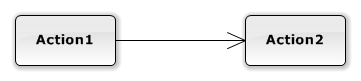
Control Flow
A control flow connects actions and activities (an action with an action, an action with an activity, an activity with an activity). It can specify a condition, which will be displayed in brackets. The condition determines whether the path can be used. Conditions are used together with decision diamonds when there are multiple possible ways of continuation.
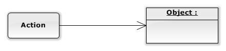
Object Flow
An object flow connects an action with an object (or with a pin) or an object with an action.
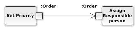
Pin
A pin represents an object. It is attached to an action. A flow of objects between actions is described using an object flow relationship.
Initial Node
An initial node is a starting point of the modeled activity flow.

Flow Final Node
A flow final node terminates flows that reach this node.

Activity Final Node
An activity final node terminates all flows in an activity. An activity diagram can contain multiple nodes of this kind. The first reached activity final node stops the whole activity.

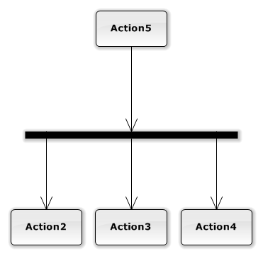
Fork
A fork element splits one incoming flow into multiple outcoming concurrent asynchronous flows.
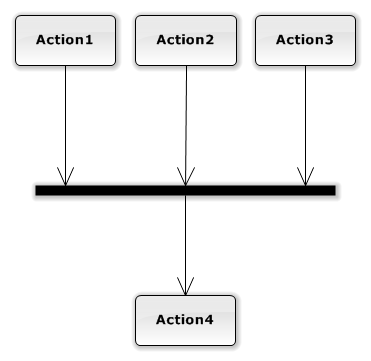
Join
A join element combines multiple incoming asynchronous flows into one outcoming flow. It stops processing until all incoming flows are completed.
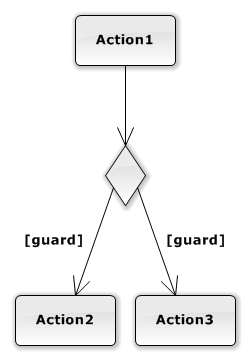
Decision
A decision element creates multiple alternative branches of the flow. Conditions in control flows decide which flow will be used. Only one outgoing flow can be used.
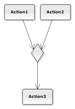
Merge
A merge element combines alternative incoming flows into the single one. Do not confuse this with the Join element. Merge is not used for synchronization of concurrent flows.
Signal Send
A signal send is an action node invokes an asynchronous event in a target object or a process.
Signal Receipt
A signal receipt is an action node that receives an asynchronous message from an object or a process.
Accept Time Event
An accept time event node represents a source of periodically generated outputs. This action is called each defined unit of time and continues with a defined flow.

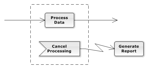
Interruptible Activity Region
An interruptible activity region represents an area of diagram which can be left by an event. This interrupting event is modeled using an exception handler relationship (a flash lightning line).
How to Draw an Activity Diagram?
You can create a new activity diagram in multiple ways:
- Click on a Plus button in the tab switch bar, navigate to UML group and click on the UML Activity Diagram item
- Press CTRL+SHIFT+D, choose Activity Diagram from the UML group, enter the name and click on the OK button.
- Switch to Project tab in the ribbon and click on the Activity Diagram item in the Content gallery.
- Open Project sidebar, right-click on a project (or a folder) node, and in the Add Diagram submenu, choose UML Activity Diagram.
Set an Actor as a Swimlane Representation
You can set an actor to represent a swimlane very easily. Just drag the actor from the project tree and drop it over the swimlane caption.
Switch Swimlane Orientation
When drawing a swimlane, its orientation is chosen automatically as horizontal, or vertical depending on the longer side. However, you may want to create a wide vertical swimlane or high horizontal swimlane. Or you just change your mind, and you want to set a different orientation later. You do not need to draw the swimlane again. Just select the swimlane and click on the Switch Orientation button in the context bar.How to Draw Activity Diagram Elements?
How to Draw a Swimlane?
- Click on the Swimlane button in the Activity Diagram group in the toolbox
- Specify the bounds of the new swimlane by dragging on the diagram canvas
- If you want to add a swimlane with the default size, just click on a diagram canvas and the swimlane will be inserted to the specified position
- If you want to insert multiple swimlanes in a row, double click (or click twice) on the Swimlane button in the toolbox, and draw swimlanes in the diagram editor
How to Draw an Initial Node?
- Click on the Initial Node button in the Activity Diagram group in the toolbox
- If you want to add an initial node with the default size, just click on a diagram canvas and the initial node will be inserted to the specified position
- If you want to add an initial node with a custom size, click on the desired position on the diagram and drag to define the size of the new initial node.
- If you want to insert multiple initial nodes in a row (e.g. for several UML activities or activity regions), double click (or click twice) on the Initial Node button in the toolbox, and draw initial nodes in the diagram editor
How to Draw an Activity Final Node?
- Click on the Activity Final Node button in the Activity Diagram group in the toolbox
- If you want to add an activity final node with the default size, just click on a diagram canvas and the activity final node will be inserted to the specified position
- If you want to add an activity final node with a custom size, click on the desired position on the diagram and drag to define the size of the new activity final node.
- If you want to insert multiple activity final nodes in a row (e.g. for several UML activities or activity regions), double click (or click twice) on the Activity Final Node button in the toolbox, and draw as many activity final nodes as you want in the diagram editor
How to Draw a Flow Final Node?
- Click on the Flow Final Node button in the Activity Diagram group in the toolbox
- If you want to add a flow final node with the default size, just click on a diagram canvas and the flow final node will be inserted to the specified position
- If you want to add a flow final node with a custom size, click on the desired position on the diagram and drag to define the size of the new flow final node.
- If you want to insert multiple flow final nodes in a row (e.g. for several UML activities or activity regions), double click (or click twice) on the Flow Final Node button in the toolbox, and draw flow final nodes in the diagram editor
How to Draw an Activity?
- Click on the Activity button in the Activity Diagram group in the toolbox
- If you want to add an Activity with the default size, just click on a diagram canvas and the activity will be inserted to the specified position
- If you want to add an activity with a custom size, click on the desired position on the diagram and drag to define the size of the new Activity.
- If you want to insert multiple activities in a row, double click (or click twice) on the Activity button in the toolbox, and draw activities in the diagram editor
How to Draw an Activity Parameter?
The easiest way how to add an activity parameter to a diagram is to select an activity element and click on the Add Parameter button in the context bar.
- Another way is, to click on the Activity Parameter button in the Activity Diagram group in the toolbox
- If you want to add an activity parameter with the default size, just click on a diagram canvas and the swimlane will be inserted to the specified position
- If you want to add an activity parameter with a custom size, click on the desired position on the diagram and drag to define the size of the new activity parameter.
- If you want to insert multiple activity parameters in a row (e.g. for several UML activities or a single activity), double click (or click twice) on the Activity Parameter button in the toolbox, and draw activity parameters in the diagram editor
How to Draw an Object?
- Click on the Object button in the Activity Diagram group in the toolbox
- If you want to add an object with the default size, just click on a diagram canvas and the object will be inserted to the specified position
- If you want to add an object with a custom size, click on the desired position on the diagram and drag to define the size of the new Object.
- If you want to insert multiple objects in a row, double click (or click twice) on the Object button in the toolbox, and draw objects in the diagram editor.
How to Draw an Action?
- Click on the Action button in the Activity Diagram group in the toolbox
- If you want to add an action with the default size, just click on a diagram canvas and the action will be inserted to the specified position
- If you want to add an action with a custom size, click on the desired position on the diagram and drag to define the size of the new Action.
- If you want to insert multiple actions in a row, double click (or click twice) on the Action button in the toolbox, and draw actions in the diagram editor
How to Draw a Call Behavior Action?
- Click on the Call Behavior Action button in the Activity Diagram group in the toolbox.
- If you want to add a call behavior action with the default size, just click on a diagram canvas and the call behavior action will be inserted to the specified position.
- If you want to add a call behavior action with a custom size, click on the desired position on the diagram and drag to define the size of the new call behavior action.
- If you want to insert multiple call behavior actions in a row (e.g. for several UML activities or activity regions), double click (or click twice) on the Call Behavior Action button in the toolbox and draw swimlanes in the diagram editor.
How to Draw a Fork?
- Click on the Fork button in the Activity Diagram group in the toolbox.
- If you want to add a fork with the default size, just click on a diagram canvas and the fork will be inserted to the specified position.
- If you want to add a fork with a custom size, click on the desired position on the diagram and drag to define the size of the new fork.
- If you want to insert multiple forks in a row, double click (or click twice) on the Fork button in the toolbox, and draw the desired number of forks in the diagram editor.
How to Draw a Join?
- Click on the Join button in the Activity Diagram group in the toolbox.
- If you want to add a join with the default size, just click on a diagram canvas and the join will be inserted to the specified position.
- If you want to add a join with a custom size, click on the desired position on the diagram and drag to define the size of the new join.
- If you want to insert multiple joins in a row, double click (or click twice) on the Join button in the toolbox and draw the desired number of joins in the diagram editor.
How to Draw a Decision?
- Click on the Decision button in the Activity Diagram group in the toolbox.
- If you want to add a decision with the default size, just click on a diagram canvas and the decision will be inserted to the specified position.
- If you want to add a decision with a custom size, click on the desired position on the diagram and drag to define the size of the new decision.
- If you want to insert multiple decisions in a row, double click (or click twice) on the Decision button in the toolbox, and draw the desired number of decisions in the diagram editor.
How to Draw a Merge?
- Click on the Merge button in the Activity Diagram group in the toolbox.
- If you want to add a merge with the default size, just click on a diagram canvas and the merge will be inserted to the specified position.
- If you want to add a merge with a custom size, click on the desired position on the diagram and drag to define the size of the new merge.
- If you want to insert multiple merges in a row, double click (or click twice) on the Merge button in the toolbox, and draw the desired number of merges in the diagram editor.
How to Draw a Pin?
The easiest way how to add a pin to a diagram is to select an action element and click on the Add Pin button in the context bar.
- Click on the Pin button in the Activity Diagram group in the toolbox.
- If you want to add a pin with the default size, just click on a diagram canvas and the pin will be inserted to the specified position
- If you want to add a pin with a custom size, click on the desired position on the diagram and drag to define the size of the new pin.
- If you want to insert multiple pins in a row (e.g. for several UML actions), double click (or click twice) on the Pin button in the toolbox, and draw pins in the diagram editor.
How to Draw a Signal Send?
- Click on the Signal Send button in the Activity Diagram group in the toolbox.
- If you want to add a signal send element with the default size, just click on a diagram canvas and the signal send will be inserted to the specified position.
- If you want to add a signal send element with a custom size, click on the desired position on the diagram and drag to define the size of the new signal send element.
- If you want to insert multiple signal send elements in a row, double click (or click twice) on the Signal Send button in the toolbox, and draw the desired number of signal send elements in the diagram editor.
How to Draw a Signal Receipt?
- Click on the Signal Receipt button in the Activity Diagram group in the toolbox.
- If you want to add a signal receipt element with the default size, just click on a diagram canvas and the signal receipt will be inserted to the specified position.
- If you want to add a signal receipt element with a custom size, click on the desired position on the diagram and drag to define the size of the new signal receipt element.
- If you want to insert multiple signal receipt elements in a row, double click (or click twice) on the Signal Receipt button in the toolbox, and draw the desired number of signal receipt elements in the diagram editor.
How to Draw an Accept Time Event Action?
- Click on the Accept Time Event Action button in the Activity Diagram group in the toolbox.
- If you want to add an accept time event action with the default size, just click on a diagram canvas and the accept time event action will be inserted to the specified position.
- If you want to add an accept time event action with a custom size, click on the desired position on the diagram and drag to define the size of the new accept time event action.
- If you want to insert multiple accept time event actions in a row, double click (or click twice) on the Accept Time Event Action button in the toolbox and draw the desired number of accept time event actions in the diagram editor.
How to Draw an Expansion Region?
- Click on the Expansion Region button in the Activity Diagram group in the toolbox.
- If you want to add an expansion region with the default size, just click on a diagram canvas and the expansion region will be inserted to the specified position.
- If you want to add an expansion region with a custom size, click on the desired position on the diagram and drag to define the size of the new expansion region.
- If you want to insert multiple expansion regions in a row, double click (or click twice) on the Expansion Region button in the toolbox, and draw the desired number of expansion regions in the diagram editor.
How to Draw an Expansion Region Node?
- Click on the Expansion Region Node button in the Activity Diagram group in the toolbox.
- If you want to add an expansion region node with the default size, just click on a diagram canvas and the expansion region node will be inserted to the specified position.
- If you want to add an expansion region node with a custom size, click on the desired position on the diagram and drag to define the size of the new expansion region node.
- If you want to insert multiple expansion region nodes in a row, double click (or click twice) on the Expansion Region Node button in the toolbox, and draw the desired number of expansion region nodes in the diagram editor.
How to Draw a Conditional Node?
- Click on the Conditional Node button in the Activity Diagram group in the toolbox.
- If you want to add a conditional node with the default size, just click on a diagram canvas and the conditional node will be inserted to the specified position.
- If you want to add a conditional node with a custom size, click on the desired position on the diagram and drag to define the size of the new conditional node.
- If you want to insert multiple conditional nodes in a row, double click (or click twice) on the Conditional Node button in the toolbox, and draw the desired number of conditional nodes in the diagram editor.
How to Draw a Loop Node?
- Click on the Loop Node button in the Activity Diagram group in the toolbox.
- If you want to add a loop node with the default size, just click on a diagram canvas and the loop node will be inserted to the specified position.
- If you want to add a loop node with a custom size, click on the desired position on the diagram and drag to define the size of the new loop node.
- If you want to insert multiple loop nodes in a row, double click (or click twice) on the Loop Node button in the toolbox, and draw the desired number of loop nodes in the diagram editor.
How to Draw a Connector?
- Click on the Connector button in the Activity Diagram group in the toolbox.
- If you want to add a connector with the default size, just click on a diagram canvas and the connector will be inserted to the specified position.
- If you want to add a connector with a custom size, click on the desired position on the diagram and drag to define the size of the new connector.
- If you want to insert multiple connectors in a row, double click (or click twice) on the Connector button in the toolbox, and draw the desired number of connectors in the diagram editor.
How to Draw a Control Flow?
- Click on the Control Flow button in the Activity Diagram group in the toolbox.
- Drag from a start element (e.g. action) to an end element (e.g. another action, decision, etc.)
- Another way you can connect two elements with a control flow is to click on the Control Flow button in the toolbox and drag it in between two elements (e.g. actions). The diagram shows you which two elements will be connected when you release the button.
- If you want to insert multiple control flows in a row, double click (or click twice) on the Control Flow button in the toolbox, and draw the desired number of control flows in the diagram editor.
How to Draw an Object Flow?
- Click on the Object Flow button in the Activity Diagram group in the toolbox.
- Drag from a start element (e.g. action) to an end element (e.g. another action, decision, etc.)
- Another way you can connect two elements with an object flow is to click on the Object Flow button in the toolbox and drag it in between two elements (e.g. actions). The diagram shows you which two elements will be connected when you release the button.
- If you want to insert multiple object flows in a row, double click (or click twice) on the Object Flow button in the toolbox, and draw the desired number of object flows in the diagram editor.
New Comment