UML State Machine Diagram Tutorial
State Machine Diagram in UML
A state machine diagram is a behavior UML diagram. It depicts the transitions between particular states. The initial state indicates the state that the modeled object starts in. The final state refers to the state where the activity of the modeled object ends.State Machine Types
A state machine diagram may be one of two types:
- Protocol state machine
- Behavior state machine
The type of state machine diagram can be set using Diagram Properties dialog - State Machine tab.
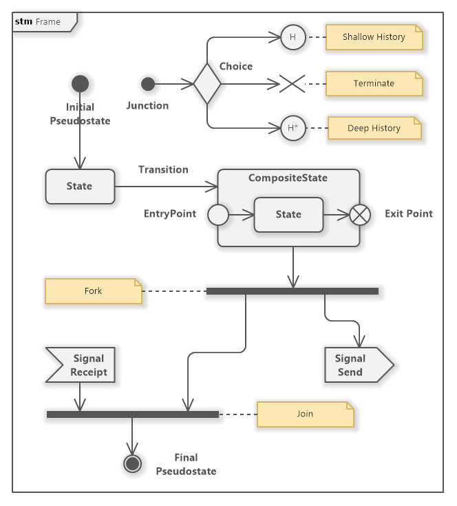
State Machine Symbols
Software Ideas Modeler offers tools for following elements of a state machine diagram:
- Initial Pseudostate - Represents the starting point of a state machine or a composite state. It's depicted as a solid circle and indicates the default state when the system or composite state is initialized.
- Final Pseudostate - Symbolized by a circle with a dot inside, it denotes the end of a state machine or composite state's lifecycle. Reaching this state means the state machine or composite state has completed its execution.
- State - A rectangle with rounded corners that represents a condition during the life of an object where it satisfies some condition, performs some activity, or waits for some event.
- Composite State - A state that contains other states (substates). It's depicted as a rectangle with rounded corners and a divider. The upper part contains the name, and the lower part shows nested states, indicating that the system can be in more than one substate at a time.
- Fork - A pseudostate used to split a transition into multiple parallel paths. It's represented by a thick line that transitions into several outgoing paths, indicating concurrent state activities.
- Join - A pseudostate that brings together multiple parallel paths into one. It's depicted as a line where several incoming transitions converge into a single outgoing transition, synchronizing parallel processes.
- Choice - Denoted by a diamond shape, it represents a decision point where the transition path is selected based on guard conditions or events, leading to different outcome states.
- Signal Receipt - Indicates that a state is waiting to receive a specific signal or event to trigger a transition.
- Signal Send - Represents the action of sending a signal or event from a particular state, which can trigger transitions in the same or different state machine.
- Transition - A solid line with an arrowhead that connects two states, indicating a change from one state to another. Transitions are triggered by events and may have associated actions or conditions.
- Protocol Transition - A special kind of transition used in protocol state machines to specify legal transitions for operations.
- Entry Point - A pseudostate that serves as a connection point for entering a composite state from an external transition. It's represented by a small circle with a name.
- Exit Point - A pseudostate for exiting a composite state, allowing for an external transition to another state. It's shown as a small circle with a diagonal cross inside.
- Deep history - A pseudostate that remembers the most deeply nested active state configuration. When a state machine re-enters the composite state containing a deep history, it will return to the remembered state. It's depicted as a circle with an "H*" inside.
- Shallow History - Similar to deep history but remembers only the top-level state configuration. On re-entry, the state machine returns to the last active substate of the composite state. It's represented by a circle with an "H" inside.
- Terminate Node - A special kind of final state that not only ends the state machine or composite state but also terminates the object's existence. It's depicted as a diagonal cross.
- Junction - A small circle that can be used to chain together multiple transitions. It allows for more complex transition paths without specifying conditions directly on transitions.
- Frame - A container that encapsulates the entire state machine diagram or parts of it, usually with a name to indicate the context or the state machine's name.
What is a State?
A state represents a specific life span of an object defined by constraints. An object in a given state shows specific behavior. The reactions of an object to the same inputs may differ depending on the object state.
If an object is in a given state it fulfills the invariant condition. The invariant is usually implicit. You can also define the invariant condition explicitly. Then it is displayed in the brackets under the state name.
A state may define three activities that are performed depending on a state change.
- Entry - if a state is changed to this state, the entry activity is performed.
- Do - the behavior that is performed while the object is in this state.
- Exit - if this state is left and it is changed to another state, the exit activity is performed.
Video Tutorial on How to Create a UML State Machine Diagram
For those who prefer a more visual and interactive learning experience, our tutorial on creating UML State Machine diagrams is complemented by an invaluable video tutorial section. This video guide meticulously walks you through the process of setting up and detailing a UML State Machine diagram, specifically focusing on the usage of trigger events to model complex system behaviors. For a comprehensive walkthrough, please refer to the linked article: How to Create UML State Machine Diagram with Trigger Events
How to Draw a State Machine Diagram?
You can create a new state machine diagram in multiple ways:
- Click on a Plus button in the tab switch bar, navigate to UML group and click on the UML State Machine Diagram item
- Press CTRL+SHIFT+D, choose State Machine Diagram from the UML group, enter the name and click on the OK button.
- Switch to Project tab in the ribbon and click on the State Machine Diagram item in the Content gallery.
- Open Project sidebar, right-click on a project (or a folder) node, and in the Add Diagram submenu, choose UML State Machine Diagram.
Greville Earle 4 August 2023 11:05:31
State actions
Dusan Rodina - softwareideas.net 4 August 2023 22:26:35
RE: State actions
Will Hui 11 February 2024 18:21:19
Behavior Expression
Dusan Rodina - softwareideas.net 14 February 2024 9:45:54
RE: Behavior Expression