UML Class Diagram Tutorial
Class Diagram in UML
A class diagram is one of 7 structure diagrams in UML notation. It depicts a static structure of a modeled system, module, or its part. The basic building block of a class diagram is a class - a unit that represents a set of objects with the same attributes and logic. The diagram can also represent a data model of a specific domain.Class Diagram Purpose
Class diagrams may be used in various scenarios primarily in software development, but also other areas for:
- Static structure design and analysis
- System responsibilities modeling
- Software reverse engineering
- Source code generation and scaffolding
UML Class Diagram Symbols
Software Ideas Modeler offers tools for following elements of a class diagram:
- Package
- Class
- Interface
- Enumeration
- Structure
- Table
- Signal
- Collaboration
- Usage
- Association
- Unidirectional Association
- Bidirectional Association
- N-ary Association
- Composition
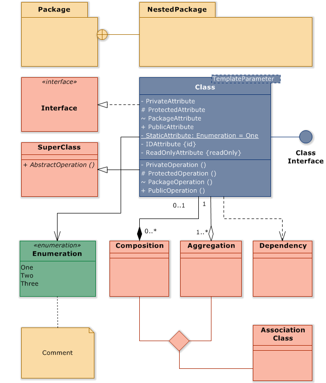
Class
A class is an extensible template for creating objects, it is a common form for all instances of the same type (e.g. concept, thing, person). A class that cannot have any instances is called an abstract class.Each class can contain:
- Attributes
- Operations
- Template parameters
- Stereotypes
- Tagged values
- Documentation
Visibility
Visibility determines the scope, in which can be attributes and operations seen and manipulated by other objects. UML defines these symbols for the visibility of members (attributes or operations)
| Symbol | Visibility | Meaning |
|---|---|---|
| + | Public | Defines a member that is accessible from the whole project. |
| ~ | Package | Defines a member that is accessible from the whole package. |
| # | Protected | Defines a member that is accessible from the class and its subclasses. |
| - | Private | Defines a member that is accessible only from the class, where it is specified. |
Attribute
An attribute is a named data field within a classifier, which determines allowed data using its type, multiplicity, and constraints. Each class can have zero or more attributes. Attributes are defined within an attribute compartment (placed after name compartment) of a classifier.
Attribute format: <<stereotypes>> visibility_symbol name : type [multiplicity ordering] = default_value {constraint}
Abstract attributes are indicated by italic.
Static attributes are indicated by underline.
Software Ideas Modeler offers several ways how to add, edit, and delete attributes of a class:
- using menu Element / Add / Attribute
- using context bar button Add Attribute
- using Properties dialog
- using Fast editor
Each attribute is defined by:
- Name
- ID
- Type
- Visibility
- Default Value
- Multiplicity
- Ordering
- Constraint
- Modifiers
- Stereotypes
- Documentation
- Tagged Values
Operation
Operation is a method, function, or query, which can be called by other objects. Each operation has its name and it can have any number of parameters (zero or more). Each operation should perform only one thing. Operations are defined within an operation compartment (placed after the attribute compartment) of a classifier.
Operation format: <<stereotypes>> visibility_symbol name (parameter1 ... parameterN) : return_type
Abstract operations are indicated by italic.
Static operations are indicated by underline.
Software Ideas Modeler offers several ways how to add, edit, and delete operations of a class:
- using menu Element / Add / Operation
- using context bar button Add Operation
- using Properties dialog
Each operation is defined by:
- Name
- ID
- Return type
- Visibility
- Modifiers
- Stereotypes
- Parameters
- Body
- Documentation
- Tagged Values
Operation Parameter
Operation Parameter is usually an input argument, although it may be also an output or input-output argument.
Operation format: direction name : type [multiplicity]
Each operation parameter can be defined using:
- Name
- Type
- Direction - it can be input (in), output (out), input-output (inout) or return
- Default value
- Multiplicity
- Documentation
- Tagged values
Association
The association is a type of relationship in the UML class diagram. It can be depicted as a simple line connector or with decorated ends. The association may be specialized as aggregations and compositions that have some differences. The association can specify its cardinality and navigability.
What is Aggregation?
An aggregation is a kind of the "has-a" association relationship. It is an association that represents a part-whole or part-of relationship. Diamond arrow points from a part to a whole.

What is Composition?
A composition is a stronger kind of the "has-a" association relationship. It is similar to the aggregation, but it is more specific. The existence of a part (connected with composition) is dependent on the whole.

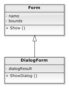
Generalization
A generalization specifies the relationship between a superclass and its subclass. Arrow points from a subclass to a superclass. A superclass represents a base for subclasses. The subclasses provide more details about their superclass. A subclass inherits functionality from its superclasses.
For example, a Dialog Form (subclass) is a more specific type of Form (superclass) - the generalization arrow points from DialogForm class to Form class.
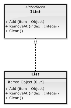
Realization
A realization specifies a dependency relationship between an interface and a class, where a class implements the specified interface. Arrow points from a class to an interface. A realization relationships indicate that the class realizes the connected interfaces. The realization class has to conform to the realized interfaces - that means implement all the defined operations. The class can be optionally refined by other additional operations.
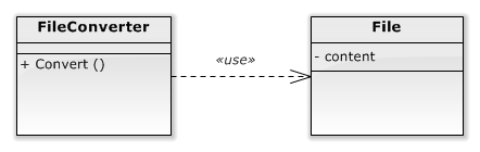
Dependency
A dependency specifies a relationship between two dependent classes. The arrow points to the class that is used by the second class.
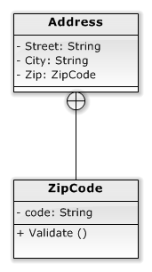
Containment
A containment specifies a relationship between a parent class and a nested inner class. A containment relationship is depicted with a circle with a plus on one end. The circle end is attached to the container and the unmarked end of the connector is attached to the contained class. Containment is used to depict nested or inner classes - the classes defined within another class.
Package
A package is a general-purpose container element for grouping of elements, which represent a logical, semantical, or another unit. A package can be contained in other packages. Each package defines its namespace.
Interface
An interface is an abstract element that defines operations that must be implemented in a classifier. A classifier is connected to implemented interfaces using realization relationships.
Enumeration
An enumeration is a user-defined type, which consists of enumerated literals/named values. An enumeration element represents a type with enumerated literal values that may be used for attributes, operations and operation parameters.N-ary Association
An n-ary association is depicted as a diamond in the class diagram. It connects more than two classes in a single association.
How to Draw a Class Diagram?
You can create a new class diagram in multiple ways:
- Click on a Plus button in the tab switch bar, navigate to UML group and click on the UML Class Diagram item
- Press CTRL+SHIFT+D, choose Class Diagram from the UML group, enter the name and click on the OK button.
- Switch to Project tab in the ribbon and click on the Class Diagram item in the Content gallery.
- Open Project sidebar, right-click on a project (or a folder) node, and in the Add Diagram submenu, choose UML Class Diagram.
How to Draw Class Diagram Elements?
How to Draw a Class?
- Click on the Class button in the Class Diagram group in the toolbox.
- Specify the bounds of the new class by dragging on the diagram canvas.
- If you want to add a class with the default size, just click on a diagram canvas and the class will be inserted to the specified position. You can also drag the Class button from the toolbox and drop it to the desired position on the diagram.
- If you want to insert multiple classes in a row, double click (or click twice) on the Class button in the toolbox and draw so many classes as you want in the diagram editor. If you do not want to add others, press the ESC key or click to the Selection tool button.
After creating a class in the diagram, you can add these fields to it:
- attributes - click on the button Add Attribute in the context bar.
- operations - click on the button Add Operation in the context bar.
- rules (or constraints) - click on the button Add Rule in the context bar.
- constructors - click on the button Add Constructor in the context bar.
How to Draw a Package?
- Click on the Package button in the Class Diagram group in the toolbox.
- Specify the bounds of the new package by dragging on the diagram canvas. If the bounds cover other elements in the diagram, they will be added to the package as nested elements.
- If you want to add a package with the default size, just click on a diagram canvas and the package will be inserted to the specified position. You can also drag the Package button from the toolbox and drop it to the desired position on the diagram.
- If you want to insert multiple packages in a row, double click (or click twice) on the Package button in the toolbox and draw as many packages as you want in the diagram editor.
How to Draw an Interface?
- Click on the Interface button in the Class Diagram group in the toolbox.
- Specify the bounds of the new interface by dragging on the diagram canvas.
- If you want to add an interface with the default size, just click on a diagram canvas and the interface will be inserted to the specified position. You can also drag the Interface button from the toolbox and drop it to the desired position on the diagram.
- If you want to insert multiple interfaces in a row, double click (or click twice) on the Interface button in the toolbox and draw desired number of interfaces in the diagram editor. If you do not want to add others, press the ESC key or click to the Selection tool button.
After creating an interface, you can add attributes, operations and rules to it using the context bar buttons.
How to Draw an Enumeration?
- Click on the Enumeration button in the Class Diagram group in the toolbox.
- Specify the bounds of the new enumeration by dragging on the diagram canvas.
- If you want to add an enumeration with the default size, just click on a diagram canvas and the enumeration will be inserted to the specified position. You can also drag the Enumeration button from the toolbox and drop it to the desired position on the diagram.
- If you want to insert multiple enumerations in a row, double click (or click twice) on the Enumeration button in the toolbox and draw desired number of enumerations in the diagram editor. If you do not want to add others, press the ESC key or click to the Selection tool button.
After creating an enumeration in the diagram, you can add enumeration items to it using the context bar button Add Item.
How to Draw a Structure?
- Click on the Structure button in the Class Diagram group in the toolbox.
- Specify the bounds of the new structure by dragging on the diagram canvas.
- If you want to add a structure with the default size, just click on a diagram canvas and the structure will be inserted to the specified position. You can also drag the Structure button from the toolbox and drop it to the desired position on the diagram.
- If you want to insert multiple structures in a row, double click (or click twice) on the Structure button in the toolbox and draw desired number of structures in the diagram editor. If you do not want to add others, press the ESC key or click to the Selection tool button.
How to Draw a Table?
- Click on the Table button in the Class Diagram group in the toolbox.
- Specify the bounds of the new table by dragging on the diagram canvas.
- If you want to add a table with the default size, just click on a diagram canvas and the table will be inserted to the specified position. You can also drag the Table button from the toolbox and drop it to the desired position on the diagram.
- If you want to insert multiple tables in a row, double click (or click twice) on the Table button in the toolbox and draw desired number of tables in the diagram editor. If you do not want to add others, press the ESC key or click to the Selection tool button.
How to Draw a Signal?
- Click on the Signal button in the Class Diagram group in the toolbox.
- Specify the bounds of the new signal by dragging on the diagram canvas.
- If you want to add a signal with the default size, just click on a diagram canvas and the signal will be inserted to the specified position. You can also drag the Signal button from the toolbox and drop it to the desired position on the diagram.
- If you want to insert multiple signals in a row, double click (or click twice) on the Signal button in the toolbox and draw desired number of signals in the diagram editor. If you do not want to add others, press the ESC key or click to the Selection tool button.
How to Draw a Collaboration?
- Click on the Collaboration button in the Class Diagram group in the toolbox.
- If you want to add a collaboration with the default size, just click on a diagram canvas and the collaboration will be inserted to the specified position.
- If you want to add a collaboration with a custom size, click on the desired position on the diagram and drag to define the size of the new collaboration.
- If you want to insert multiple collaborations in a row, double click (or click twice) on the Collaboration button in the toolbox and draw as many collaborations as you want in the diagram editor.
How to Draw a Generalization?
- Click on the Generalization button in the Class Diagram group in the toolbox.
- Drag from a sub-class to a super-superclass.
- Another way you can insert a generalization relationship between two classes is to click on the Generalization button in the toolbox and drag it in between two class elements. The diagram editor shows you which two classes will be connected when you release the button.
- If you want to insert multiple generalizations in a row, double click (or click twice) on the Generalization button in the toolbox and draw the desired number of generalizations in the diagram editor.
How to Draw a Realization?
- Click on the Realization button in the Class Diagram group in the toolbox.
- Drag from a classifier to an interface. The arrow points from a classifier to an interface.
- Another way you can insert a realization relationship between a classifier and an interface is to click on the Realization button in the toolbox and drag it in between an interface and a classifier. The diagram editor shows you which two elements will be connected when you release the button.
- If you want to insert multiple realizations in a row, double click (or click twice) on the Realization button in the toolbox and draw the desired number of realizations in the diagram editor.
How to Draw an Association?
- Click on the Association button in the Class Diagram group in the toolbox.
- Drag from an element to another element. The inserted association is undirected.
- Another way you can insert an association between two elements (e.g. classes) is to click on the Association button in the toolbox and drag it in between two elements. The diagram editor shows you which two elements will be connected when you release the button.
- If you want to insert multiple associations in a row, double click (or click twice) on the Association button in the toolbox and draw the desired number of associations in the diagram editor.
How to Draw a Containment?
- Click on the Containment button in the Class Diagram group in the toolbox.
- Drag from an element (e.g. class, instance specification) that should be contained to another element (e.g. class, instance specification) that contains the start element. The inserted relationship points from contained element to its container.
- Another way you can insert a containment between two elements is to click on the Containment button in the toolbox and drag it in between two elements. The diagram editor shows you which two elements will be connected in the containment relationship when you release the button.
- If you want to insert multiple associations in a row, double click (or click twice) on the Containment button in the toolbox and draw the desired number of containments in the diagram editor.
Class Diagram Examples
You may find some examples of UML class diagram here:
- UML Class Diagram Overview (UML Class Diagram)
- Restaurant Orders (UML Class Diagram)
- Adapter Design Pattern (UML Class Diagram)
- Linked Lists (UML Class Diagrams)
- DMS - Document Management System (Project, Diagrams)
- Logger (Model of Extensible Logging Module)
- Command Stack (Diagram)
- Nervous System (UML Class Diagram)
- Haematopoiesis - Immune System (UML Class Diagram)
- Library Management System (UML Class Diagram)
- Hospital Management System (UML Diagrams)
- Medical Examination (N-ary Association Example)
- Purchase N-ary Example (UML Class Diagram)
KC 24 March 2016 23:39:36
Attributes of attributes
Dusan Rodina - softwareideas.net 25 March 2016 2:12:50
RE: Attributes of attributes
Bruno Santos 30 October 2017 17:46:29
Association multiplicity
Dusan Rodina - softwareideas.net 30 October 2017 18:40:51
RE: Association multiplicity
Aleksandar 18 October 2022 19:59:19
Java
Dusan Rodina - softwareideas.net 18 October 2022 21:49:40
RE: Java
Adalberto J. Brasaca 26 July 2024 15:58:33
Collection Attribute
Rod Montrose 17 October 2024 0:34:43
Multiple Generalizations
Dusan Rodina - softwareideas.net 17 October 2024 13:53:12
RE: Multiple Generalizations