UML Communication Diagram Tutorial
A UML communication diagram shows interactions in the form of messages between objects and parts, which are represented by lifelines. Communication Diagram is a modified form of UML Sequence Diagram, but unlike it, its elements do not have to be ordered horizontally and may have any position in the diagram.
Communication Diagram in UML
A communication diagram is an interaction behavior UML diagram. It depicts the communication between objects (called lifelines) through messages.Communication Diagram in UML
Communication Diagram Symbols
Software Ideas Modeler offers tools for following elements of a communication diagram:
- Lifeline
- Message
- Swimlane
- Actor
- Generalization
- Dependency
Diagram Example
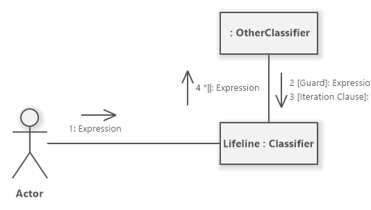
UML Communication Diagram Example
How to Draw a Communication Diagram?
You can create a new communication diagram in multiple ways:
- Click on a Plus button in the tab switch bar, navigate to UML group and click on the UML Communication Diagram item
- Press CTRL+SHIFT+D, choose Communication Diagram from the UML group, enter the name and click on the OK button.
- Switch to Project tab in the ribbon and click on the Communication Diagram item in the Content gallery.
- Open Project sidebar, right-click on a project (or a folder) node, and in the Add Diagram submenu, choose UML Communication Diagram.
Create a new UML communication diagram
How to Draw Communication Diagram Elements?
How to Draw a Lifeline?
- Click on the Lifeline button in the Communication Diagram group in the toolbox.
- Specify the bounds of the new lifeline by dragging on the diagram canvas.
- If you want to add a lifeline with the default size, just click on a diagram canvas and the actor will be inserted to the specified position.
- If you want to insert multiple lifelines in a row, double click (or click twice) on the Lifeline button in the toolbox and draw as many lifelines as you want in the diagram editor.
How to Draw an Actor?
- Click on the Actor button in the Communication Diagram group in the toolbox.
- Specify the bounds of the new actor by dragging on the diagram canvas.
- If you want to add an actor with the default size, just click on a diagram canvas and the actor will be inserted to the specified position.
- If you want to insert multiple actors in a row, double click (or click twice) on the Actor button in the toolbox and draw as many actors as you want in the diagram editor.
How to Draw a Message?
- Click on the Message button in the Communication Diagram group in the toolbox.
- Drag from a lifeline (or an actor) to another lifeline (or an actor).
- Another way you can insert a message connector between two elements (lifelines, actors) is to click on the Message button in the toolbox and drag it in between two elements. The diagram editor shows you which two elements will be connected when you release the button.
- If you want to insert multiple messages in a row, double click (or click twice) on the Message button in the toolbox and draw the desired number of messages in the diagram editor.
How to Draw a Generalization?
- Click on the Generalization button in the Communication group in the toolbox.
- Drag from a sub-actor to a super-actor.
- Another way you can insert a generalization relationship between two actors is to click on the Generalization button in the toolbox and drag it in between two actor elements. The diagram editor shows you which two elements will be connected when you release the button.
- If you want to insert multiple actors in a row, double click (or click twice) on the Generalization button in the toolbox and draw the desired number of generalizations in the diagram editor.
New Comment