UML Object Diagram Tutorial
Object Diagram in UML
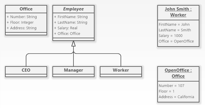
An object diagram is a structural UML diagram. It shows instances of classes, and their associations.Object Diagram Symbols
Software Ideas Modeler offers tools for following elements of an object diagram:
- Instance Specification (Object)
- Class
- Association
- Generalization
- Containment
Diagram Example
How to Draw an Object Diagram?
You can create a new object diagram in multiple ways:
- Click on a Plus button in the tab switch bar, navigate to UML group and click on the UML Object Diagram item
- Press CTRL+SHIFT+D, choose Object Diagram from the UML group, enter the name and click on the OK button.
- Switch to Project tab in the ribbon and click on the Object Diagram item in the Content gallery.
- Open Project sidebar, right-click on a project (or a folder) node, and in the Add Diagram submenu, choose UML Object Diagram.
Instance Specification
Instance specification represents a snapshot of a class or a structure at a specific time. The instance specification element is linked to a class and its attributes. It specifies values for the particular class attributes. The values may be literals, instances or enumeration items.
Create an Instance Specification of a Class
To create an instance specification, drag the Instance Specification button from the toolbox to the diagram canvas. You can associate a class with the instance specification in many ways:
- drag a classifier from the project tree (Project sidebar) and drop it over an instance specification element
- drag a classifier using right mouse button from a diagram, drop it over an instance specification element and choose Set Representing Element from the context menu
- enter the name of a classifier after the instance name and the colon when editing the name of the instance specification in the diagram editor
Add Attributes to Instance Specification
You may add an attribute to an instance specification using the Properties dialog or directly from the diagram editor. Click on the 'Add Attribute' button in the context bar (below the selected element) and choose attributes you want to add from the list in the Attributes dialog. This dialog will show only if a classifier is associated with the instance specification. If there is not any classifier specified, an attribute with a default name (which you may change) is added to the instance specification.
How to Draw Object Diagram Elements?
How to Draw an Instance Specification?
- Click on the Instance Specification button in the Object Diagram group in the toolbox.
- Specify the bounds of the new instance specification by dragging on the diagram canvas.
- If you want to add an instance specification with the default size, just click on a diagram canvas and the instance specification will be inserted to the specified position.
- If you want to insert multiple instance specifications in a row, double click (or click twice) on the Instance specification button in the toolbox and draw as many instance specifications as you want in the diagram editor. When you add the last one, press ESC or switch to another tool by clicking on its button.
How to Draw a Class?
- Click on the Class button in the Object Diagram group in the toolbox.
- Specify the bounds of the new class by dragging on the diagram canvas.
- If you want to add a class with the default size, just click on a diagram canvas and the class will be inserted to the specified position.
- If you want to insert multiple classes in a row, double click (or click twice) on the Class button in the toolbox and draw so many classes as you want in the diagram editor. If you do not want to add others, press ESC or click to the Selection tool button.
How to Draw an Association?
- Click on the Association button in the Object Diagram group in the toolbox.
- Drag from an element to another element. The inserted association is undirected.
- Another way you can insert an association between two elements is to click on the Association button in the toolbox and drag it in between two elements. The diagram editor shows you which two elements will be connected when you release the button.
- If you want to insert multiple associations in a row, double click (or click twice) on the Association button in the toolbox and draw the desired number of associations in the diagram editor.
How to Draw a Containment?
- Click on the Containment button in the Object Diagram group in the toolbox.
- Drag from an element (e.g. class, instance specification) that should be contained to another element (e.g. class, instance specification) that contains the start element. The inserted relationship points from contained element to its container.
- Another way you can insert a containment between two elements is to click on the Containment button in the toolbox and drag it in between two elements. The diagram editor shows you which two elements will be connected in the containment relationship when you release the button.
- If you want to insert multiple associations in a row, double click (or click twice) on the Containment button in the toolbox and draw the desired number of contaiments in the diagram editor.
How to Draw a Generalization?
- Click on the Generalization button in the Object Diagram group in the toolbox.
- Drag from a sub-class to a super-class.
- Another way you can insert a generalization relationship between two classes is to click on the Generalization button in the toolbox and drag it in between two class elements. The diagram editor shows you which two elements will be connected when you release the button.
- If you want to insert multiple generalizations in a row, double click (or click twice) on the Generalization button in the toolbox and draw the desired number of generalizations in the diagram editor.
New Comment