UML Component Diagram Tutorial
Component Diagram in UML
A component diagram is one of the UML structural diagrams. It shows a structure of modules within a system or between systems. It models interfaces between the system components - the interfaces required by components, the interfaces provided by components, and dependencies between the components and their interfaces.
What is a Component Diagram?
A component diagram is a high-level architecture diagram. It may be used for depicting the structure of component-based systems. Components can be grouped into bigger components. A component can consist of other nested components. Hierarchical structures may be created this ways.
What is a Component?
A component is an integral part of a system with a publicly defined interface, it may be a module, a program, a dynamically linked library, a subsystem, or a service.
What is an Artifact?
An artifact is a physical piece of information that is produced by a software system as a part of the modeled process. It can be a file, a document, a database table, an email message, or other types of textual or binary files. An artifact may consist of other artifacts.
What is an Interface?
An interface provides a list of public methods through which the systems can communicate. A system (or a component) provides an interface and another system (or a component) expects an interface of a specific type. Two systems that know this interface can communicate with each other without knowing their internal implementation or platform.
What is a Component Design?
A component design separates the reusable modules into components with well-documented interfaces. Components are reused within a larger system as an opposing to copy-paste programming. The particular components can produce and consume messages via events.
Component Diagram Concepts
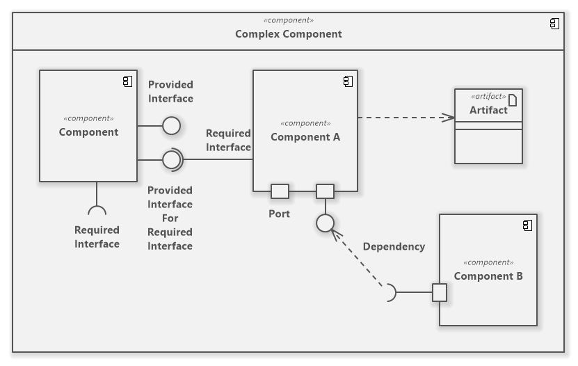
Complex Component
Apart from simple components, you will often need complex components in the system modeling. Software Ideas Modeler allows you to insert multiple nested components into a component to define the internal structure of the complex component. To create one, drag a component from the toolbox and drop it over the desired component in the diagram editor. A simple component will automatically switch to a complex component with an internal structure.
UML Component Diagram Overview
Component Diagram Symbols
Software Ideas Modeler offers tools for following elements of a component diagram:
- Component
- Port
- Provided Interface
- Required Interface
- Collaboration
- Artifact
- Class
- Interface
- Association
- Unidirectional Association
- Bidirectional Association
- Composition
- Aggregation
- Generalization
- Realization
- Abstraction
- Dependency
- Substitution
- Containment
- Connector
How to Draw a Component Diagram?
You can create a new component diagram in multiple ways:
- Click on a Plus button in the tab switch bar, navigate to UML group and click on the UML Component Diagram item
- Press CTRL+SHIFT+D, choose Component Diagram from the UML group, enter the name and click on the OK button.
- Switch to Project tab in the ribbon and click on the Component Diagram item in the Content gallery.
- Open Project sidebar, right-click on a project (or a folder) node, and in the Add Diagram submenu, choose UML Component Diagram.
New Comment