UML Composite Structure Diagram Tutorial
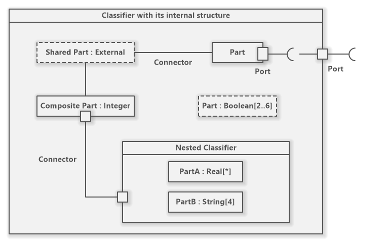
A composite structure diagram shows the internal structure of a classifier, its parts and ports via which it communicates with the environment. It models collaborations where each element has its defined role.
Composite Structure Diagram in UML
A composite structure diagram is a structure UML diagram. It depicts internal parts of a classifier and its interfaces.Composite Structure Diagram in UML
Composite Structure Diagram Overview
UML Composite Structure
Composite Structure Diagram Symbols
Software Ideas Modeler offers tools for following elements of a composite structure diagram:
- Class
- Part
- Port
- Interface
- Required Interface
- Collaboration
- Association
- Unidirectional Association
- Bidirectional Association
- Composition
- Aggregation
- Generalization
- Realization
- Dependency
- Containment
How to Draw a Composite Structure Diagram?
You can create a new composite structure diagram in multiple ways:
- Click on a Plus button in the tab switch bar, navigate to UML group and click on the UML Composite Structure Diagram item
- Press CTRL+SHIFT+D, choose Composite Structure Diagram from the UML group, enter the name and click on the OK button.
- Switch to Project tab in the ribbon and click on the Composite Structure Diagram item in the Content gallery.
- Open Project sidebar, right-click on a project (or a folder) node, and in the Add Diagram submenu, choose UML Composite Structure Diagram.
Create a new UML composite structure diagram
How to Draw Composite Structure Diagram Elements?
How to Draw a Class?
- Click on the Class button in the Composite Structure Diagram group in the toolbox.
- Specify the bounds of the new class by dragging on the diagram canvas.
- If you want to add a class with the default size, just click on a diagram canvas and the class will be inserted to the specified position.
- If you want to insert multiple classes in a row, double click (or click twice) on the Class button in the toolbox and draw so many classes as you want in the diagram editor. If you do not want to add others, press the ESC key or click to the Selection tool button.
How to Draw a Data Type?
- Click on the Data Type button in the Composite Structure Diagram group in the toolbox.
- Specify the bounds of the new data type by dragging on the diagram canvas.
- If you want to add a data type with the default size, just click on a diagram canvas and the data type will be inserted to the specified position.
- If you want to insert multiple data types in a row, double click (or click twice) on the Data Type button in the toolbox and draw the desired number of data types in the diagram editor. If you do not want to add others, press the ESC key or click to the Selection tool button.
How to Draw a Part?
- Click on the Part button in the Composite Structure Diagram group in the toolbox.
- Specify the bounds of the new part by dragging on the diagram canvas. The part should be drawn within bounds of a class.
- If you want to add a part with the default size, drag the Part button from the toolbox and drop it over the desired position over a classifier on a diagram canvas.
- If you want to insert multiple parts in a row, double click (or click twice) on the Part button in the toolbox and draw the desired number of parts in the diagram editor. If you do not want to add others, press the ESC key or click to the Selection tool button.
How to Draw a Port?
- Click on the Port button in the Composite Structure Diagram group in the toolbox.
- Specify the bounds of the new port by dragging on the diagram canvas. The port should be drawn on the border of a class or part. You can draw a nested port inside another port.
- If you want to add a port with the default size, drag the Port button from the toolbox and drop it over the desired position over a class or part on a diagram canvas. You can also drop the port over another port and create a nested port.
- If you want to insert multiple ports in a row, double click (or click twice) on the Port button in the toolbox and draw the desired number of ports in the diagram editor. If you do not want to add others, press the ESC key or click to the Selection tool button.
How to Draw a Provided Interface?
- Click on the Provided Interface button in the Composite Structure Diagram group in the toolbox.
- Start dragging from a provided interface owner (e.g. class, port) and stop where the interface's circle (“lollipop”) should be placed.
- If you want to add a provided interface with the default placement, just drag the Provided Interface button from the toolbox and drop it over the desired element (class, part, port) in the diagram editor.
- If you want to insert multiple interfaces in a row, double click (or click twice) on the Provided Interface button in the toolbox and draw the desired number of provided interfaces in the diagram editor. If you do not want to add others, press the ESC key or click to the Selection tool button.
How to Draw a Required Interface?
- Click on the Required Interface button in the Composite Structure Diagram group in the toolbox.
- Start dragging from a required interface owner (e.g. class, port) and stop where the interface's arc should be placed.
- If you want to add a required interface with the default placement, just drag the Required Interface button from the toolbox and drop it over the desired element (class, part, port) in the diagram editor.
- If you want to insert multiple interfaces in a row, double click (or click twice) on the Required Interface button in the toolbox and draw the desired number of required interfaces in the diagram editor. If you do not want to add others, press the ESC key or click to the Selection tool button.
How to Draw a Collaboration?
- Click on the Collaboration button in the Composite Structure Diagram group in the toolbox.
- If you want to add a collaboration with the default size, just click on a diagram canvas and the collaboration will be inserted to the specified position.
- If you want to add a collaboration with a custom size, click on the desired position on the diagram and drag to define the size of the new collaboration.
- If you want to insert multiple collaborations in a row, double click (or click twice) on the Collaboration button in the toolbox and draw as many collaborations as you want in the diagram editor.
How to Draw an Association?
- Click on the Association button in the Composite Structure Diagram group in the toolbox.
- Drag from an element to another element. The inserted association is undirected.
- Another way you can insert an association between two elements is to click on the Association button in the toolbox and drag it in between two elements. The diagram editor shows you which two elements will be connected when you release the button.
- If you want to insert multiple associations in a row, double click (or click twice) on the Association button in the toolbox and draw the desired number of associations in the diagram editor.
How to Draw a Containment?
- Click on the Containment button in the Composite Structure Diagram group in the toolbox.
- Drag from an element (e.g. class, instance specification) that should be contained to another element (e.g. class, instance specification) that contains the start element. The inserted relationship points from contained element to its container.
- Another way you can insert a containment between two elements is to click on the Containment button in the toolbox and drag it in between two elements. The diagram editor shows you which two elements will be connected in the containment relationship when you release the button.
- If you want to insert multiple associations in a row, double click (or click twice) on the Containment button in the toolbox and draw the desired number of containments in the diagram editor.
How to Draw a Generalization?
- Click on the Generalization button in the Composite Structure Diagram group in the toolbox.
- Drag from a sub-class to a super-class.
- Another way you can insert a generalization relationship between two classes is to click on the Generalization button in the toolbox and drag it in between two class elements. The diagram editor shows you which two elements will be connected when you release the button.
- If you want to insert multiple generalizations in a row, double click (or click twice) on the Generalization button in the toolbox and draw the desired number of generalizations in the diagram editor.
New Comment