What is Entity-Relationship Diagram (ERD)?
What Is an ER Diagram?
The entity-relationship diagram (ERD) is one of the most fundamental and important design tools in the database designer's toolbox. It shows how a database can be organized in terms of entities, relationships, and attributes. It is a graphical representation of the entity-relationship model of a database in which it illustrates the relationships between the logical entities that make up an information system.
An ERD diagram depicts the data model of a system (or its part) using entities that represent data types and relationships that define the dependencies between entities. The ER diagrams are used for designing database schemas. Attributes, primary and foreign keys are defined as a part of the particular entities.
Entity-relationship (ER) modeling is a data modeling technique that represents real world entities and their relationships in a database.
ERD Elements and Symbols
This diagram type provides 2 basic kinds of elements:
- Entity - represents a data type or a database table
- Relationship - connects entities, it expresses how they are related to each other
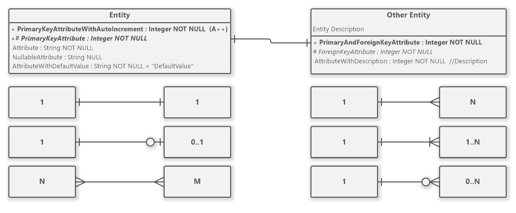
Other symbols may be used as a part of an attribute definition:
- Plus (+) - represents a primary key attribute
- Hash (#) - represents a foreign key attribute
- Key symbol - represents a primary key attribute
- Bent Arrow symbol - represents a foreign key attribute
ERD Entity
An entity is specified by its attributes. It may also include its indexes. Except for standard documentation, the entity may provide its description. An attribute is defined by these parameters:
- Name
- Primary key
- Foreign key
- Nullability - NULL or NOT NULL
- Default Value
- Type
- Description
- Auto Increment
What is a Primary Key?
The primary key is a unique identifier of a row of an entity/table. It is an important concept within a relational database design. The relationship between entities may exist only because of primary keys. They serve as a reference for the particular row of data. A primary key cannot be a NULL value. It may be of any data type, but the smaller ones are preferable. An entity cannot contain two rows with the same values for its primary key. An entity may have only one primary key.
What is Foreign Key?
The foreign key connects a row (where it is specified) with a row from another or the same entity/table. It may contain a NULL value. The value of a foreign key refers to a primary key in another table (or even in the same table as it is defined). Unlike the primary key, the foreign key values may repeat within an entity.
What is Nullability?
The nullability specifies whether an attribute of an entity may or may not contain a NULL value. When you design entities for your database you should pay attention to whether a NULL value is really needed or not. The NULL value represents a missing or undefined value. When a foreign key contains NULL value it means that it does not refer to any primary key.
What is a Default Value?
The default value defines a value that should be used when no value is provided for a newly inserted row. The default value concept is useful, especially for bit flags. E.g. an entity may have an attribute called IsDeleted. We do not expect the newly inserted row is deleted, so we may define the default value 0 (False) and the user will not need to specify this value unless they really want to insert a "deleted" row.
ERD Relationship
A relationship shows which entity is associated with which. It also specifies cardinality (or multiplicity) of each end. These options are available:
- One (1)
- Zero or One (0..1)
- Many (N)
- Zero or Many (0..N)
- One or Many (1..N)
Cardinality in ER Diagram
A cardinality in ERD represents how many instances (rows) of an entity (table) can be associated with a target entity connected with a relationship (representing a foreign key). It can be defined in terms of a minimum and maximum number (or as a range between two numbers). Common cardinalities are: 1, *, 0..1, 1..*.
ER Diagram Variations
You may set various styles for keys, cardinality, and attribute layout to adjust the diagram style to fit your preferences.
The keys may be rendered as:
- Plus, Hash (+#)
- PK, FK
- Icons
The cardinality may be represented as:
- Crow's Foot (visual style)
- Min-Max (numeric style)
- Bachman (visual style)
There are two available layouts for attributes:
- Flow - the parts of attributes flow one by one
- Columns - the parts of attributes are aligned to a table
You may choose these variations in the Diagram Properties dialog. The dialog is accessible from the ribbon Diagram/Diagram Properties or from the context menu (Diagram Properties...) which shows after right-clicking a free space in the diagram canvas. The options are available on the Entity-Relationship Diagram tab.
How to Draw an Entity-Relationship Diagram?
You can create a new ER diagram in many ways:
- Click on a Plus button in the tab switch bar, navigate to Entity Relationship group and click on the Entity Relationship Diagram item
- Press CTRL+SHIFT+D, choose Entity Relationship Diagram from the Entity Relationship group, enter the name and click on the OK button.
- Switch to Project tab in the ribbon and click on the Entity Relationship Diagram item in the Content gallery.
- Open Project sidebar, right-click on a project (or a folder) node, and in the Add Diagram submenu, choose Entity Relationship Diagram from the Other submenu.
When creating an ERD, you need to follow these steps:
1. Identify the entities in the domain of the modeled system.
2. Populate attributes for the identified entities.
3. Mark the primary keys.
4. Resolve the relationships between the particular entities.
5. Set types and nullability for the attributes.
You can also watch our video tutorial about creating entity-relationship diagrams.
How to Draw ERD Elements?
How to Draw an Entity?
- Click on the Entity button in the Entity Relationship Diagram group in the toolbox.
- Specify the bounds of the new entity by dragging on the diagram canvas.
- If you want to add an entity with the default size, just click on a diagram canvas and the entity symbol will be inserted to the specified position. You can also drag the Entity button from the toolbox and drop it to the desired position on the diagram.
- If you want to insert multiple entities in a row, double click (or click twice) on the Entity button in the toolbox and draw the desired number of entities in the diagram editor. If you do not want to add any other entities, press the ESC key or click to the Selection tool button.
How to Draw a Relationship?
- Click on the Relationship button in the Entity Relationship Diagram group in the toolbox.
- Drag from an entity to another entity.
- Another way you can insert a relationship between two entities is to click on the Relationship button in the toolbox and drag it in between the desired entities. The diagram editor shows you which two elements will be connected when you release the button.
- If you want to insert multiple relationships in a row, double click (or click twice) on the Relationship button in the toolbox and draw so many relationships as you want in the diagram editor.
ER Diagram Examples
You can check out our rich collection of diagram examples. You can browse our examples of ERD and find out what is possible with our ERD tool:
- Hotel Room Booking System (Entity-Relationship Diagram)
- Users (Entity-Relationship Diagram)
- Dynamic Form Model (ERD Example)
- Invoicing - Invoice Database Model Using ERD
- Real Estate Portal (ER Diagrams)
- Employee Management System (ER diagram)
- Movie Ticket Booking System (ER Diagram)
- Event Management System (ER Diagram)
- Voting System (ER Diagram)
- Admin and User (Chen ER Diagram)
- Doctor and Patient (Chen ER Diagram)
- Food Ordering System (ER Diagram)
- Database Management System (ERD)
- University Information System (ER Diagram)
- Lecture Registration System (ERD)
All ER diagram examples can be found in the dedicated data models and ERD category.
Erik 26 February 2020 5:50:31
Keys rendered as icons?
Dusan Rodina - softwareideas.net 26 February 2020 8:13:51
RE: Keys rendered as icons?