UML Sequence Diagram Tutorial
Sequence Diagram in UML
According to UML notation, a sequence diagram is a type of behavior diagram that belongs to the interaction diagrams group.Sequence Diagram Symbols
Software Ideas Modeler offers tools for following elements of a sequence diagram:
Lifelines
- Lifeline: A representation of an individual participant in the interaction over time.
- Actor: A role played by an entity that interacts with the system modeled in the diagram.
- Boundary: Represents the interface between the system and actors or other systems, such as users or external services, which can include user interfaces like windows, screens, pages, toolbars, and menus.
- Control: Objects or elements that mediate interactions between boundaries and entities, implementing the logic required to manage their interactions and serving as the cohesive force within the system's architecture.
- Entity: An object that represents system data, often derived from the domain model, encapsulating the system's state and behavior.
Messages
- Call Message: A type of message that represents a request from one object to another to execute a procedure or operation.
- Reply Message: A message that represents the response from the receiver back to the sender after a call message.
- Send Message: A message that represents the action of sending information from one lifeline to another without expecting a reply.
- Create Message: A message that signifies the instantiation of a lifeline.
- Delete Message: A message indicating the termination of a lifeline's instance.
- Self Message: A message an object sends to itself, typically to invoke its own operations.
- Recursive Message: A specific type of self message where an operation calls itself.
- Destroy Occurrence: A notation marking the point at which an object is destroyed.
- Duration Message: A message that shows the time taken for an interaction to occur between two lifelines.
- Lost Message: A message that is sent but not received by any object within the diagram.
- Found Message: A message that arrives from an unspecified source or represents the receipt of a message.
Fragments
- Interaction Operand: A part of a combined fragment that contains a conditionally executed sequence.
- Opt Fragment: An interaction fragment that represents a sequence that occurs only under certain conditions.
- Alt Fragment: An interaction fragment that models alternative sequences, one of which is executed based on a condition.
- Loop Fragment: An interaction fragment representing a sequence that may be repeated based on a condition.
- Par Fragment: An interaction fragment that represents parallel execution paths.
- Neg Fragment: An interaction fragment that represents an invalid scenario.
- Critical Fragment: Denotes a section of interactions that cannot be interrupted, ensuring that the sequence of actions within the fragment is executed without any interference from outside messages or events.
- Strict Fragment: Indicates that the interactions within the fragment must occur in the exact order specified, with no interleaving of other messages or actions.
Other Elements
- Execution Occurrence: A bar that represents a specific period during which an element is performing an action.
- Interaction Use: A reference to another interaction, allowing for reuse of sequences in different contexts.
- State Invariant: A condition or constraint that must hold true during the execution of the interaction.
- Duration Constraint: A specification of the minimum and maximum time duration for an interaction.
- Gate: A point at which messages can enter or exit an interaction or interaction fragment.
- Coregion: An area within a lifeline where messages can occur in parallel or out of sequence.
- Concurrent
Lifeline
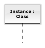
A lifeline is an element that represents an individual participant (object, actor, component, or process) in the interaction. It is rendered as a box with a name and vertical line. The line shows a time-ordered sequence of messages (from top to bottom).
Actor
An actor represents an external participant. An actor is rendered as a lifeline with a sticky man on the top in sequence diagrams.

Execution Occurrence
An execution occurrence represents a timespan from a lifetime of a participant when an operation is executed.
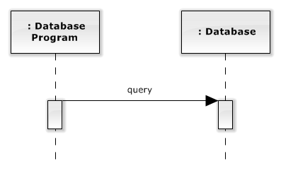
Synchronous Call Message
A synchronous call sends a message from a source lifeline to a target lifeline while all other calls of the source lifeline are blocked. Messages can be associated with a class operation. Synchronous call message is displayed as a line with a solid arrow pointing from a calling lifeline to a called lifeline.
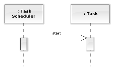
Asynchronous Call Message
An asynchronous call sends a message from a source lifeline to a target lifeline. Other calls of the source lifeline are not blocked, the next message is called immediately. Messages can be associated with a class operation. The asynchronous call message is displayed as a line with an open arrow pointing from a calling lifeline to a called lifeline.
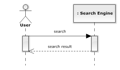
Reply Message
A reply message sends a result of execution started by call message. Reply message is displayed as a dashed line with an open arrow pointing from a replying lifeline to a calling lifeline.
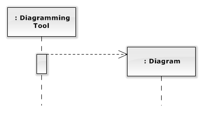
Create Message
A create message instances a new object. A create message is displayed as a dashed line with an open arrow pointing from a creating lifeline to the head of a newly created lifeline.
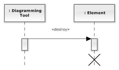
Delete Message
A delete message performs disposing of an object. It is displayed as a line with a solid arrow pointing from a lifeline which calls a delete action to a lifeline which will be deleted. The delete messages are labeled with «destroy» stereotype. A deleted lifeline has to be ended with the X symbol (destruction occurrence).
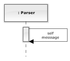
Self Message
A self message is a call message that is sent from a lifeline execution occurrence to the same occurrence.
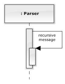
Recursive Message
A recursive message is a special case of a self-message. It models recursive calls.
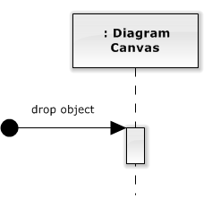
Found Message
A found message is a message with a known participant of a receiving event, but with no or unknown sending participant.
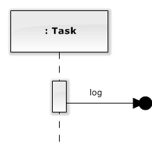
Lost Message
A lost message is a message with a known participant of an sending event, but with no or unknown receiving participant.
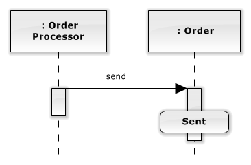
State Invariant
A state invariant represents a constraint that has to be true in the time of execution. It is displayed as a rounded rectangle.
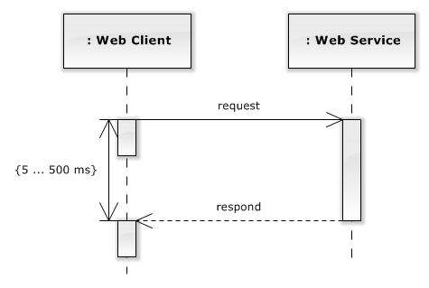
Duration Constraint
Combined Fragment
A combined fragment in UML Sequence Diagrams employs interaction operators to manage the integration of interaction operands, enabling varied paths and behaviors within an interaction. The interaction operator applied to a fragment indicates how its contained sequence of interactions should be interpreted and executed. The supported operators include:
- alt (Alternatives): Specifies alternative execution paths, with only one path executed based on a condition.
- opt (Option): Defines an optional segment of the interaction that may or may not be executed, contingent upon a specified condition.
- par (Parallel): Designates segments that can execute in parallel. Within these segments, the sequence of operations is maintained, but their execution can overlap or interleave with other parallel segments.
- critical (Critical Region): Denotes a sequence of operations that must be executed atomically, without interruption or interleaving with other operations.
- loop: Indicates a repetitive sequence of interactions, where the execution iterates based on a condition or a set number of times.
- neg (Negative): Outlines sequences that represent invalid or erroneous states within the system, typically used for specifying what should not happen.
- assert (Assertion): The operand represents an assertion that must hold true at this point in the interaction. Other continuations are considered invalid.
- strict (Strict Sequencing): Ensures that interactions within the fragment occur in a strictly sequential order, with no deviations or interleaving, maintained exactly as depicted.
- seq (Weak Sequencing): Weak sequencing between operands maintains order within each but allows occurrences across different lifelines to be flexible, adapting to parallel or strict sequencing based on the involved lifelines.
- ignore: Specifies a set of messages to be disregarded within the fragment, focusing attention on the remaining interactions.
- consider: Contrasts with ignore by explicitly listing the messages that should be considered, effectively ignoring all others not specified.
How to Draw a Sequence Diagram?
You can create a new sequence diagram in multiple ways:
- Click on a Plus button in the tab switch bar, navigate to UML group and click on the UML Sequence Diagram item
- Press CTRL+SHIFT+D, choose Sequence Diagram from the UML group, enter the name and click on the OK button.
- Switch to Project tab in the ribbon and click on the Sequence Diagram item in the Content gallery.
- Open Project sidebar, right-click on a project (or a folder) node, and in the Add Diagram submenu, choose UML Sequence Diagram.
Creating a UML Sequence Diagram: A Real-Life Example
In our comprehensive guide, we delve into the nuances of creating a UML Sequence Diagram through a detailed, real-life example: modeling an ATM transaction process. This tutorial provides step-by-step instructions on how to utilize Software Ideas Modeler to diagram the sequence of interactions between a user and an ATM. We also cover advanced diagramming techniques, including the use of alt fragments for alternative paths, loops for repetitive actions, and the inclusion of opt fragments for optional steps. This guide is an invaluable resource for anyone looking to understand the practical application of UML Sequence Diagrams in real-world scenarios.
For a thorough exploration of these concepts, please refer to our separate tutorial article here.
Sequence Diagram Examples
- Logger (Model of Extensible Logging Module)
- Command Stack (Diagram)
- ATM Withdrawal - UML Sequence Diagram for Withdrawing Money from ATM
- Login Module (UML Sequence Diagram)
- User Registration (UML Sequence Diagram)
- Shopping Cart (UML Sequence Diagram)
- Feedback System (UML Sequence Diagram)
- Report Generation System (UML Sequence Diagram)
- Taxi Booking System (UML Sequence Diagram)
- Vending Machine (UML Sequence Diagram)
- Hospital Management System (UML Diagrams)
- Online Shopping (UML Sequence Diagram)
Antonio 4 November 2021 9:52:29
Generate from c# Code
Dusan Rodina - softwareideas.net 5 November 2021 13:48:41
RE: Generate from c# Code